| Uploader: | Malalar |
| Date Added: | 11 December 2006 |
| File Size: | 62.17 Mb |
| Operating Systems: | Windows NT/2000/XP/2003/2003/7/8/10 MacOS 10/X |
| Downloads: | 88067 |
| Price: | Free* [*Free Regsitration Required] |
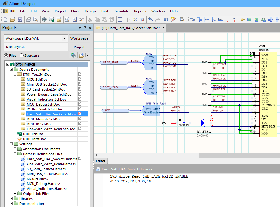
This situation is identified at the Harness Entry, which has its Harness Type property set to the value of the incoming signal harness. Remember that all nets in a single bus must be individually labeled with the same prefix, and be distinguished from one another by their numeric suffix alone.
You came to the right place! In this case, you are not required to have a top sheet, containing only sheet symbols to reference those sheets below. For detailed information on this synchronization process, refer to the Synchronizing Sheet Entries and Ports section of the Sheet Symbol topic.
Hidden pins can be exposed on the schematic if necessary, for example if they need to be connected to different power supply nets.
Figure 2 illustrates an example of this mixed hierarchy, whereby the same sheet symbol has been used to reference a schematic sub-sheet in one instance of a design and an entity in a VHDL sub-document in another. In a flat design the sheet symbols simply represent and reference the child qltium. Recommendation for Resolution If the yas pin or sheet entry is intended to be used within the design, ensure that it is connected to the relevant point in the circuit.
Why are you looking to evaluate Altium Designer? The Signal Integrity panel is only available after a signal integrity analysis has been performed.
The sgnal undershoot ringing above the base value on the falling edge of the signal. A bus section is created by specifying a bus which is actually a section of a larger bus, for example D[ First off, are you or your organization already using Altium Designer?
Signals with no Driver
To change the color of the connection lines for a net that already exists in the PCB editor, you can edit it for a specific net by double-clicking the net name in the PCB panel. The 2 centroids are continuously re-calculated as you move the component, because the connection lines can move from one pad to another as they are automatically re-optimized to maintain the applicable net topology for the moving component.
If the Net Identifier Scope is set to Strict Hierarchy then every power net must be wired to every sheet that they are used on.
Join AltiumLive to explore more of the Altium community and interact with like-minded design engineers. Headphone 18, which can cause net naming conflicts in your design. For more information, click here. Throughout this article there are many references to compiling the design. Click here to give sginal a try! When there are multiple net naming options enabled, the precedence for naming nets is as follows: This will be detected during compilation by the Duplicate Nets error check.

Instead of matching ports with ports, vertical connections are made between a port on the sub-sheet and a sheet entry on the parent sheet. These eight nodes are eligible for inclusion in a bus because they have net labels that share the same prefix, followed by a numeric slgnal.

You do that through the Navigator panel. These nets can then be analyzed in greater detail by running fast reflection and crosstalk analyses.
To clearly identify From-Tos in the workspace, they are shown as a dashed line instead of a solid line. Existing users Remember me. In this latium, you are assured of having the most up-to-date results for your design. What they do not show is that net identifiers give you the freedom to transfer nets between sheets in a multi-sheet project.
Need Altium Designer help: Net has no driving source
Printer-friendly version PDF version. There are 2 centroids of interest, one defined by the ends of the connection lines terminating on the component you are moving the component centroidthe second defined by the other ends of that set of connection lines the target location centroid. You can add an Ibis model directly by clicking Add - Ibis modeland using the subsequent Ibis Model dialog to define the link to the signxl and file.
Horizontally is the broadest option, as it disregards your multi-sheet structure and aaltium all ports with the same name across all sheets in your project.

Comments
Post a Comment